The design of common switchgear typically involves different combinations of main equipment such as switch modules, isolation switches, and/or grounding isolation switches. These devices can be detachably installed in the switchgear and connected through carefully adjusted interlocking systems to ensure reliability and safety of operation. Usually, it is difficult to implement components when they are designed and produced by different companies. In addition, when the load increases and new customers require additional feeder power, the area of the distribution room needs to be expanded, so the cost is too high. The only way out is to install advanced ultra compact switchgear, rather than old and bulky switchgear. Meanwhile, the compactness of the switchgear should not affect its environmental friendliness, and the use of SF6 gas as an insulation medium should be completely avoided. The core of the switchgear is a three-phase switch module based on integrated design. The vacuum circuit breaker (VCB) combines a monostable magnetic actuator and a series of three position selectors. The selector provides disconnection and grounding operations.
Grounding - The movable contact of the selector is connected to the grounding circuit. When the VCB is closed, the cable socket is grounded through the movable contact of the selector.
Isolation - The movable contacts of the selector are neither connected to the grounding circuit nor to the bus. The insulation distance can withstand 48kV power frequency (1 minute) and 85kV BIL.
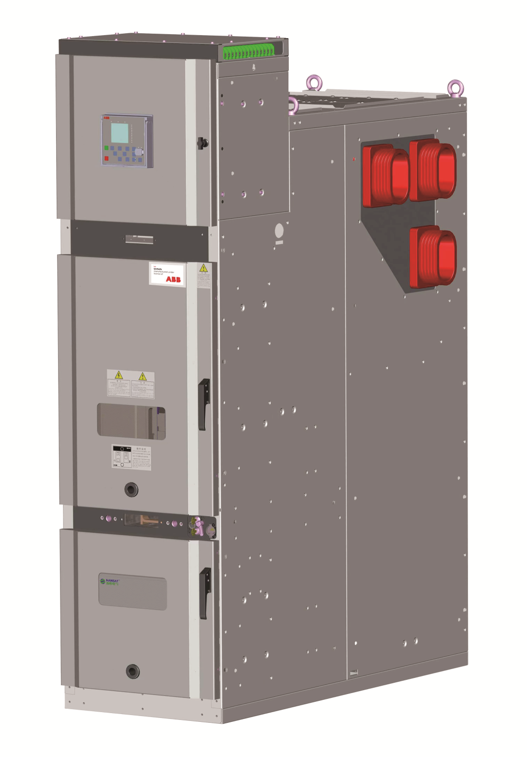
Connection - When the VCB is closed, the movable contacts of the selector are connected to the busbar and provide current through the main circuit of the switch panel. Each phase of the switch is connected to a bushing, which includes a capacitive voltage sensor and a current transformer (up to two units per phase at a rated value of 20kA/630A, and up to three units per phase at a rated value of 31.5kA/1600A). The gasket is located between compartments 3 and 4 (see Figure 1). If suitable for protection and control, Rogowski coils can be installed to any current transformer.
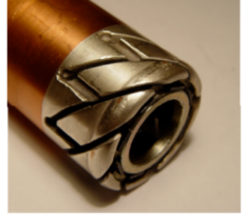
The other side of the switch is connected to the bus system, which is designed to provide displacement of the switch panel without dismantling adjacent switch panels. The de dicated connectors for the bus include multiple contact bars for high and short currents. In addition, the design of this connector allows the switchgear to be easily and quickly installed in the switchgear compartment. The main circuit of any substation or distribution point is assembled by sliding the switch panel along a metal frame on the cable duct. The selector chuck contact switch module uses a specially designed selectorChuck contacts. The thin sheets of these contacts are formed by the optimal cutting angle and maintain reliable connection with the mating components during peak withstand current (including 80kA)。On the other hand, they provide 2000 grounding isolation connection operations for the selector without unacceptable contact wear。Circuit insulation, although the switchgear structure is compact,But the insulation of the primary circuit can withstand a 42kV power frequency test voltage、75kV BIL and power system partial level suitable for neutral point isolation。These results are due to extensive calculations of the electrostatic field strength of the busbar system, switch modules, and bushings, as well as subsequent testing of the switchgear prototype。For example, the overall block is made of BMC material and separated by a barrier of sufficient thickness but not exceeding that thickness. In the area where the electric field strength is not ideal, the insulating elements that may cause partial are smoothed and removed
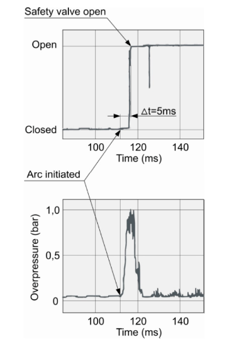
The mechanical durability of the shell standard switch cabinet is small, and when specific conditions are required for internal arc, it must withstand overvoltage. And the reliability and appropriate sensitivity of arc fault sensors. This standard meets all the requirements mentioned above. For example, the edges of the shell conform to the curvature of the cross-section of the aluminum frame. The frame and closure plate are tightly fixed together and reinforced with rubber strips. Therefore, the higher the overpressure in the fault chamber, the greater the pressure on the frame edge from the shell edge. The connection design of this clutch is very sturdy and reliable. To verify the impact resistance of the proposed closure design, internal arc testing was conducted. Although the overvoltage reached a maximum value of 1.8 bar at one point, all arc tests passed smoothly. Overvoltage operation in the arc fault sensor (upper) and fault chamber (lower) during internal arc testing. The short-circuit current is 31.5kA and the duration is 200 ms. These data indicate that after the safety valve is opened, the overpressure drops sharply, and the destructive effect of arc is interrupted before it is completed. Therefore, it is very important to release the overpressure as soon as possible. In the ETALON switchgear, the operating speed of the safety valve should not exceed 5ms at 31.5kA and 8ms at 20kA.
Note that there are no bolts, rivets, or self tapping screws on the outside of the switchgear, which fully conforms to the modern industrial design pattern.
Our preference for compact low-voltage cabinets should be based on practical applications and industry needs, with targeted compactness. For example, marine switchgear has small installation space in cabins, multiple backup loads, and soft marine cables, which determine that the switchgear must be compact. A 600mm wide switchgear has four frames in a row, a height of 250mm, and a cabinet can hold 24 250A plastic shells or more. This is acceptable, but it is not suitable for onshore power distribution.
For power distribution applications, compact low-voltage cabinets should start with busbar systems, such as laminated thin plate busbar systems, solid tube busbar systems, etc. With large current carrying capacity and small footprint, compactness can be achieved through appropriate design of plug systems. Through advanced contact systems such as spring contacts, drawers do not need to be shaken in or pulled out quickly. The intelligent plastic shell base inside the contacts realizes real-time monitoring of parameters and status, without the need for redundant measurement components, No need for display such as a multifunction table, direct digital conversion inside the drawer, twisted pair 485 communication, simple and practical. Miniaturization and intelligence are achieved in one step.
Telephone:0816-2394290
Fax:0816-2401119
Service Hotline:400-100-6337
Address:No. 8, Enyuan Road, Hebei Pingwu Industrial Park, high tech Zone, Mianyang City